Guides

Geometric Dimensioning and Tolerancing

By submitting your email you agree to receive information about relevant products and services. You may unsubscribe at any time. Read our Privacy Policy here.

What is the purpose of Geometric Dimensioning & Tolerancing?

Geometric dimensioning and tolerancing (GD&T) is a system of symbols used on engineering drawings to communicate information from the designer to the manufacturer through engineering drawings. 

GD&T tells the manufacturer the degree of accuracy and precision needed for each controlled feature of the part. GD&T is used to define the nominal geometry of parts and assemblies and to define the allowable variation of features. 

In this article: 

Common GD&T Symbols
Modifiers
Tolerance Zones
Feature Control Frames


Common GD&T Symbols

  Symbol Geometric Characteristic Feature Modifier Datums  Datum Modifier Bonus Tolerance
Form
   
 GD&T Symbol straightness Straightness
Datums Not Allowed
 
Form tolerances are defined to limit the deviations of a geometric feature from its ideal form.
       
NA ✓ Only at MMC or LMC
 GD&T Symbol flatness Flatness X NA X
 GD&T Symbol circularity Circularity X NA X
 GD&T Symbol cylindricity Cylndricity X NA X
Profile   profile of a line Profile of a line   X     Datums sometimes required  ✓   X
profile of a surface  Profile of a Surface    X  ✓   X
Orientation
GD&T Symbol angularity  Angularity
Datums Required
 
✓ Only at MMC or LMC
GD&T Symbol perpendicularity  Perpendicularity ✓ Only at MMC or LMC
GD&T Symbol parallelism  Parallelism ✓ Only at MMC or LMC
Runout
 GD&T Symbol circular run-out Circular Runout X X X
 GD&T Symbol total run-out Total Runout X X X
Location
 GD&T Symbol position Position ✓ Only at MMC or LMC
 GD&T Symbol concentricity Concentricity X X X
 GD&T Symbol symmetry Symmetry X X X

Modifiers

If no modifier follows a datum feature size, the datum feature applies regardless of material boundary.


Symbol Modifier Notes
 GD&T Symbol Continuous Feature Continuous Feature This symbol is used to identify a group of features when there is a requirement that they be teated geometrically as a single feature.
 GD&T Symbol Statistical Tolerance Statistical Tolerance Features identified as statistical toleranced should be produced with Statistical Process Control (SPC).
GD&T Symbol Envelope Requirement  Envelope requirement The upper value of a external feature defines a virtual cylinder that the entire feature has to fit inside. Likewise a internal features minimum value defines a cylinder that has to fit inside the hole.
GD&T Symbol Free State  Free State Applies only when part is otherwise restrained.
 GD&T Symbol Independency requirement Independency requirement This principle sets no limits to the number of errors of form possessed by individual features of a work piece. is the default for ISO tolerancing.
For ANSI/ASME tolerancing this has to be specified.
 GD&T Symbol Least Material Condition (LMC) Least Material Condition (LMC) Useful to maintain minimum wall thickness.
 GD&T Symbol Maximum Material Condition Maximum Material Condition Provides bonus tolerance only for a feature of size.
 Projected Tolerance Zone Projected Tolerance Zone Useful on threaded holes for long studs.
 GD&T Symbol Tangent Plane Tangent Plane Useful for interfaces where form is not required.
 GD&T Symbol Unequal Bilateral Unequal Bilateral Appears in the 2009 version of the standard, and refers to unequal profile distribution.

Tolerance Zones

Specifies the type of zone applied to the tolerance.

Symbol Tolerance zone Notes
 GD&T Symbol Controlled Radius Controlled radius Creates a tolerance zone defined by two arcs that are tangential to the adjacent surfaces
 GD&T Symbol Spherical diameter tolerance zone Spherical diameter tolerance zone Creates a spherical tolerance zone defined by a specified diameter
 GD&T Symbol Spherical Tolerance Radius Zone Spherical radius tolerance zone Creates a tolerance zone defined by two spherical segments with the minimum and maximum radii mentioned
GD&T Symbol Diameter Diameter This prefix can be used to signify that a tolerance zone exists of a diameter specified by the numerical value after this prefix.

Feature Control Frames

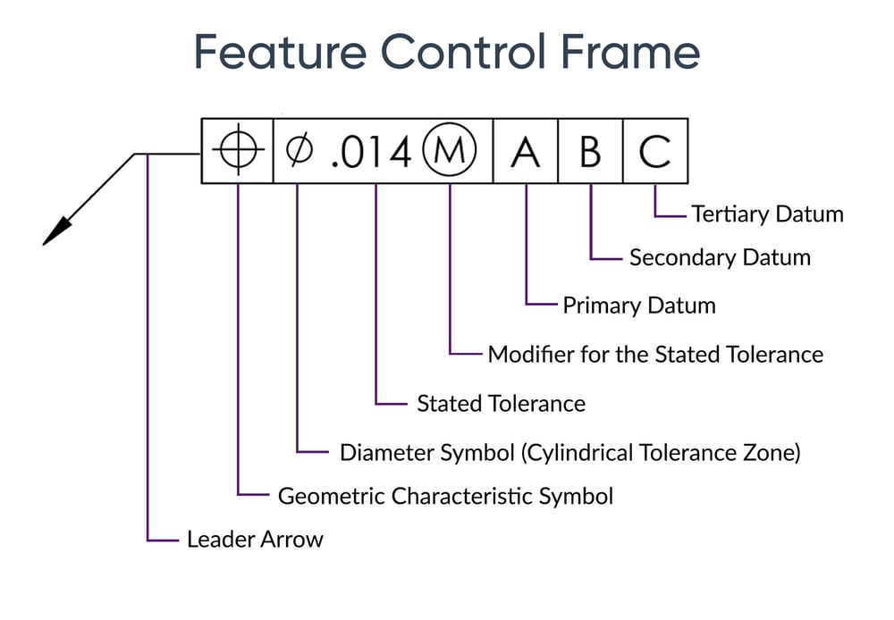
 In GD&T (Geometric dimensioning and tolerancing), a feature control frame is required to describe the conditions and tolerances of a geometric control on a part's feature. The feature control frame includes four parts: 

  • GD&T symbol/control symbol
  • Tolerance zone type and dimensions
  • Tolerance zone modifiers - such as features of size
  • Datum references (if required by the GD&T Symbol)

Combined, the feature control frame provides all the information you need to measure the geometric tolerance of the features of the part and determine if the part is in spec.

IX_Feature Control Frame


Free GD&T Font and Reference Guide

Need to use GD&T fonts in Excel for your inspection reports? Download our free GD&T font and reference guide.

What’s Included:

  • Free GD&T font files
  • Printable GD&T Reference Guide designed to print on an 8.5x11 sheet

Free GD&T Font and Reference Guide

Need to use GD&T fonts in Excel for your inspection reports? Download our free GD&T font and reference guide.

What’s Included:

  • Free GD&T font files
  • Printable GD&T Reference Guide designed to print on an 8.5x11 sheet

Save time on your inspection planning & reporting

See how you can automatically balloon GD&T callouts to create feature control frames. 

“We chose [Ideagen Quality Control] because it was easy to implement. There are training videos online, and we are able to customize reports without having to pay for services.”

Doug, Quality Engineer

Read Doug's story
Doug Murillo, Quality Engineer

Get up and running today with a free 14 day trial

Get free access