
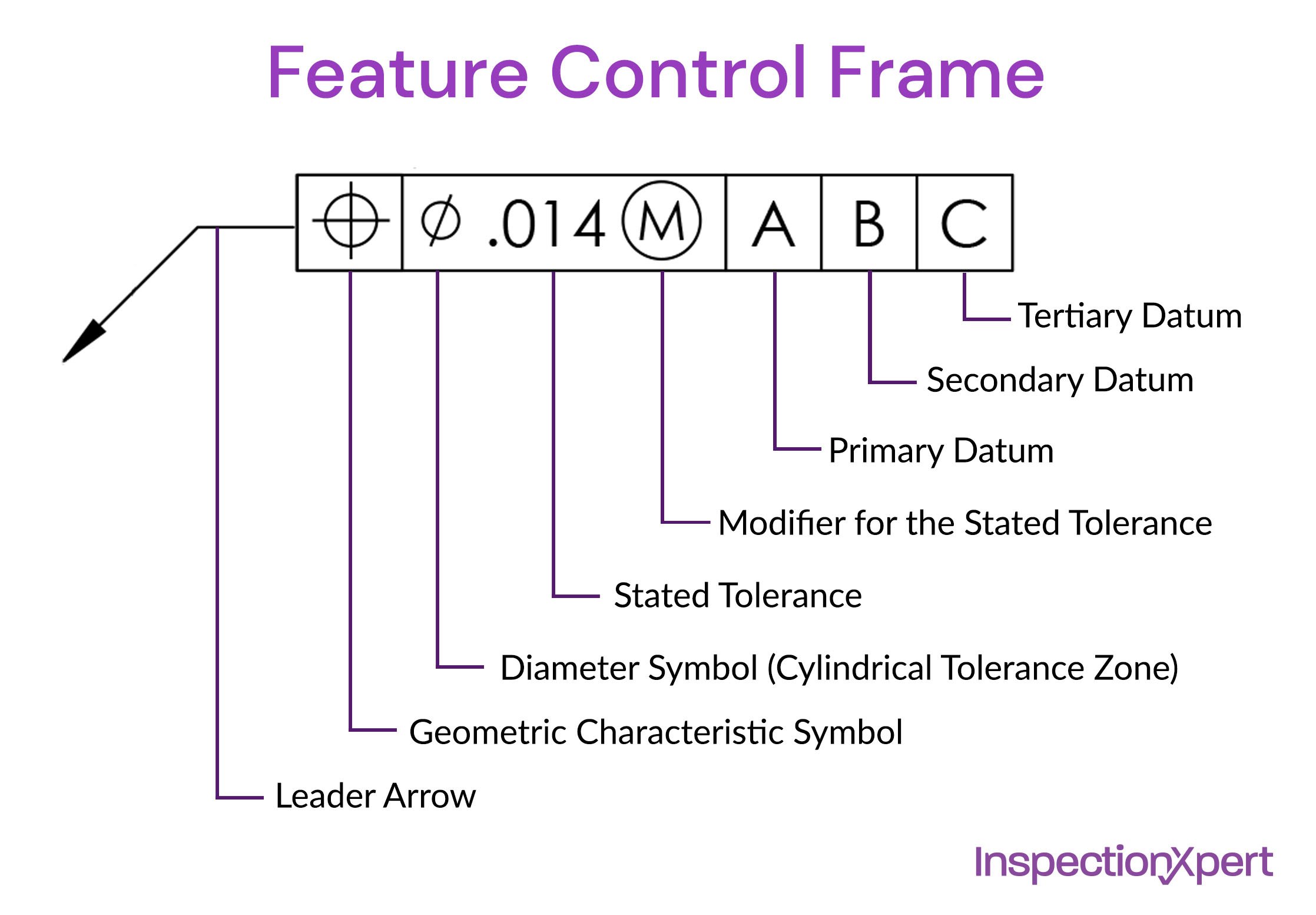
In GD&T (Geometric dimensioning and tolerancing), a feature control frame is required to describe the conditions and tolerances of a geometric control on a part's feature. The feature control frame includes four parts:
Combined, the feature control frame provides all the information you need to measure the geometric tolerance of the features of the part and determine if the part is in spec.
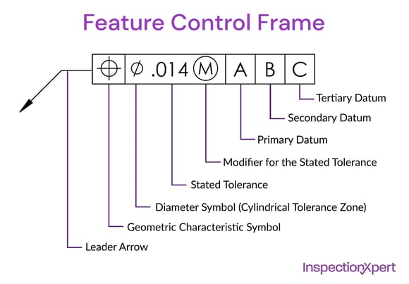
Leader Arrow
This points to the feature that the geometric control is placed on. If the arrow points to a diametric dimension, then the axis is controlled by GD&T. If the arrow points to a surface, then the surface is controlled by GD&T. The arrow is optional and may not be present on some drawings.
Geometric Characteristic Symbol
This is where geometric control is specified. Download our free GD&T Symbol Reference Guide and Font for more information.
Diameter Control / Cylindrical Tolerance Zone (if required)
If the geometric control is a diametrical tolerance then the diameter symbol will be in front of the tolerance. There are a variety of tolerance zones, see them all here.
Tolerance
The numerical value defines the tolerance zone. The unit of measure is the same for the whole drawing and will be defined in the title block.
Modifier for the Tolerance
This is max material condition or a projected tolerance in the feature control frame. See the Modifiers section of the GD&T Symbols Guide for more information on these features.
Primary Datum (if required)
If a datum is required, this is the main datum used for GD&T. The letter corresponds to a feature somewhere on the part which will be marked with the same letter. This is the datum that must be constrained first when measuring the part. The order of the datum is important for measurement of the part. The primary datum is usually in 3 places to fix 3 degrees of freedom.
Secondary Datum (if required)
When a secondary datum is required it will be to the right of the primary datum in the feature control frame. Like the primary datum the letter corresponds to a feature somewhere on the part which will be marked with the same letter. During measurement this datum is fixated after the primary datum.
Tertiary Datum (if required)
When a tertiary datum is required it is to the right of the secondary datum in the feature control frame. During measurement, this datum is fixated last.
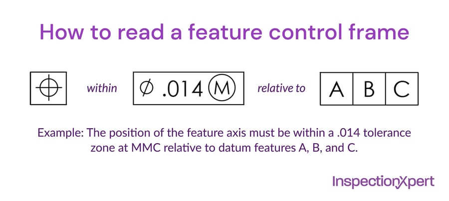
Below we look at an example of a part drawing, the GD&T calls out the 4 holes in each corner of the part, each with a diameter of 4.763. The position of the feature axis must be within a .014 tolerance zone at MMC relative to datum features A, B, and C. 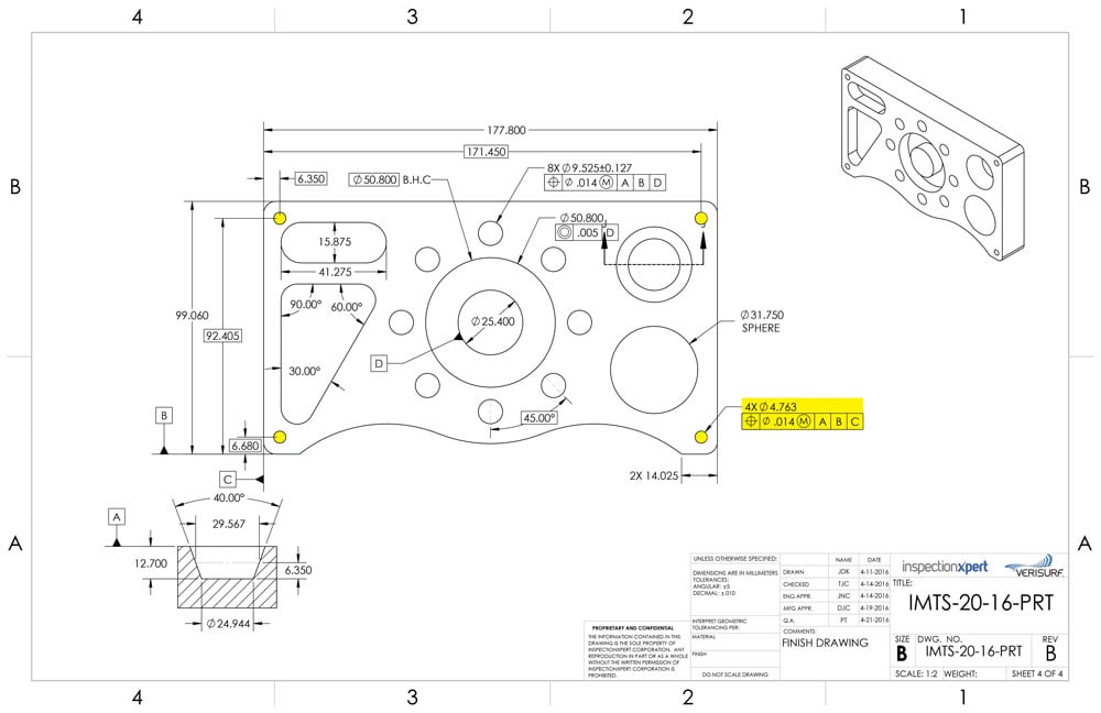
Want to learn more about geometric dimensioning and tolerancing symbols? Check out our free guide which includes free GD&T font and symbols reference guide.

Copyright 2026 Ideagen, All Rights Reserved