
A blueprint arrives on your desk for a brand new part, and you have been assigned the task of deciding what gages to use to measure everything. The secret to completing this task is to ask the right questions. And the first question to ask is “Why does my boss hate me?”
That being said, asking questions really is essential to this whole process, and it is, like everything else in the world of quality, a process. Gaging is an integral part of quality planning simply because you can't make what you can't measure. The types of gages, the frequency with which you use them, and the methods used to assure their suitability are baked into the control plan, PFEMA, FAIR, and probably the customer that brought you the order in the first place.
To get started, here are some questions you will want to explore:
First… a caveat: Many, many books have been written about each of the topics mentioned in this brief review - lots of books filled with dense mathematical formulae exploring gaussian distribution and standard deviations and… well, you get the idea. Now add the hundreds of pages of federal and industry standards governing gage design and measuring practices… and you quickly see that designing a gaging system is not as simple as it would seem.
Failure is Not an Option, but Pass / Fail Might Be
There may be times when you can use a simple fixed-limit gage that tells you Yes/No or Pass/Fail. More commonly known as an attribute gage, using it tells you if the characteristic you are measuring is good or bad to the print requirement. What it won’t tell you is by how much.
Take for example plug gages. If the Go member of the plug gage goes into a hole and the Not Go doesn’t, you can pass the part. This sort of gaging is tempting because it seems simple, easy to use and less expensive.
But - and there is always a “but” - you won’t know how close you are to the low or high limits, so you won’t be able to tell that 50 parts later, tool wear on a drill bit or a reamer will start causing every part to be undersized. In a high volume or a lights out production environment, that may force you to sort hundreds or thousands of parts to see just when they started to go bad.
Variable gaging, on the other hand, gives you a numerical result. With a variable gage you can keep an eye on how measurements change over time, enabling you to see the effects of the aforementioned tool wear, for example, on your parts. They may be more expensive and they may be harder to use, but the benefits of knowing the numbers will generally offset those concerns.
If you are active in the medical, military, aerospace, or automotive markets, chances are pretty good that your customers will require you to make variable measurements wherever you can, so you can show that you meet CPk or other process control and quality requirements.
Anything Less is Just a Guess...
Since no production process is perfect, every characteristic you measure will have a “target value”, often called the nominal, and an acceptable range of values that are higher or lower, or both, called the tolerance (not including reference and basic dimensions, which do not have tolerances, for you purists in the crowd). Tolerance will usually be expressed in your blueprint as a nominal number plus and/or minus some amount, as in a distance of 2.50 ± .001” or an angle of 45 ± 1° or a weight of 24.250 + 0 / - .250g.
Although its origin is lost in the mists of time, best measurement practices call for you to use what industry insiders call the 10 to 1 rule. Gages need to be ten times more sensitive than the tolerance of the characteristic you are measuring. So to properly measure 1.000” ± .005”, which has an overall tolerance of .010”, you need a gage with the ability to measure .001” or one-tenth of the tolerance. Anything less is just a guess.
That’s not too hard to do when tolerances are .010, .020 or even .030”. But tolerances continue to shrink as machines have become able to create finer and finer features. Tolerance ranges of less than .001” are becoming common. So imagine a part that is turned on a lathe with a blueprint that calls out a finished size of .375 + 0 / - .0004”. Total tolerance is only 4 tenths of 1/1000 of an inch. You will need a gage that can discriminate changes as small as 1/40000 of an inch.
This Gage Will Absolutely Vary
Calipers, micrometers, bore gages, and the like are all examples of variable gages. What they all have in common is that they give you a number as a result, rather than a Pass/Fail or Yes/No answer. It may not always be the number you want, but it will be a number. Variable gages themselves come in two flavors: absolute and comparative.
An absolute gage, like a micrometer, gives you a direct measurement. Once you have checked the micrometer by measuring a known object like a pin or a gage block, you are good to go. The micrometer will give a direct reading of your part’s diameter. If you measure a part with a .750” nominal, you might get a number like .7497, which is the actual size of the part in question.
A bore gage, on the other hand, has to be set using a known “master” ring before you use it. The master ring will usually be the same size as the measurement you need to make, so you would set a bore gage with a .500 master to measure a .500” hole coming out of a vertical machining center. The bore gage compares your result to the set point and tells you the difference between the two. A result of -.0003” tells you that the hole is three tenths of a thousandth under the nominal of .500.
A Pair of W’s: Who and Where
The conditions under which you measure something can have a significant effect on what gages to use.
Lighting: You can’t measure what you can’t see. The lines inscribed on many measuring devices are very small; you need ample light to be able to see them. Check any inspection standards that apply to your job - some may actually require a minimum amount of light for your inspection area.
Temperature: No matter what gage you use, make sure the gage and the part you are measuring are at the same temperature. Metals contract and expand more than you might think depending on the temperature. When tolerances are tight, even differences as small as a degree or two can make a big difference.
Training: Be sure your operators are trained on how to use the gages you do select. Show them how to check each one against a known standard at the beginning of each shift and regularly throughout the day.
Are you planning to have your machinists and operators measure parts on the shop floor at the point of production, in the presence of poor lighting, machine oil, dirt, vibration, and temperature variations? Or do you plan to check them in a pristine quality lab, where experienced professionals wearing crisp white lab coats in a controlled environment will apply sophisticated measurement technologies to obtain precise results?
If you are making more than a few parts, chances are pretty good that you will be making most of your measurements, especially the critical ones, out on the shop floor. The quality lab, with its controlled environment and high-tech equipment like CMMs, optical comparators, and computerized digital everything, is probably already running at capacity performing dozens of other tasks.
The Gage Pyramid
So, knowing all this, what gages should you use?
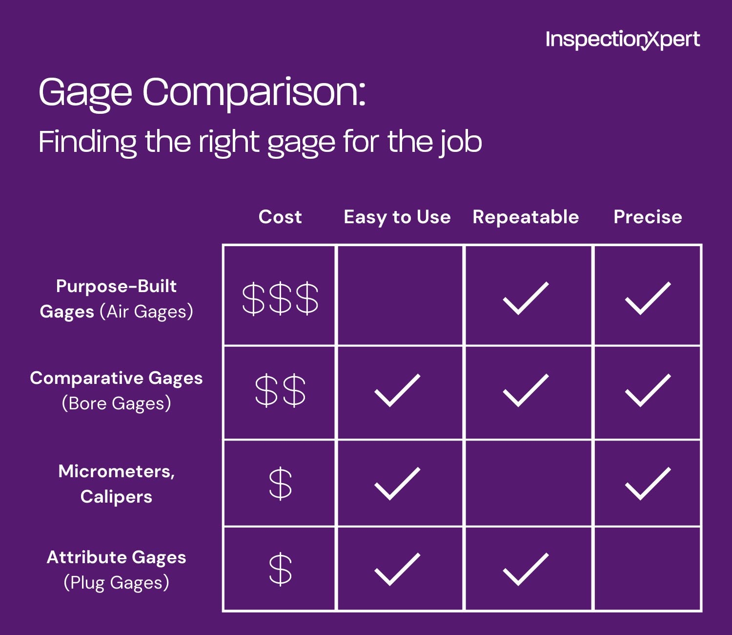
At the lower end of the measuring gage pyramid are micrometers and calipers. While digital versions of these two venerable gages are capable of discriminating down to .0001”, they are highly susceptible to error caused by user technique. Two inspectors using the same gage to measure the same part under the same conditions can get wildly different results.
Comparative gages are the next level up in terms of giving repeatable and reproducible results. A good example of this would be a variable snap gage. It is quick and easy to use, very repeatable and, with a digital indicator, easily applicable to measurements with tolerances as low as .0005”. But they are still susceptible to human error, especially bore gages, which have to be manually centered. Gage pins (also called plug gages), depending on their class, can also belong at the bottom. Check a gagemaker’s tolerance chart to see where your plug gages fall.
At the top of the pyramid are so-called purpose-built, dedicated gages, like air gages, which have a measuring head specially made for just one measurement. While an air gage, for example, is more expensive and more complicated than most handheld gages, it is highly accurate and repeatable, and essentially immune to operator-induced error. All you do with an air gage is insert the gage into the part or put the part into the gage.
No, It Does NOT Mean “Rest and Recreation”
When several gages will work for a given measurement, evaluate factors such as cost, measurement time, training, ease of use, and gage wear. A gage that is less expensive might not be better if it takes longer to make the needed measurements. Similarly, a gage that is faster might not be suitable if it costs a lot more to acquire and use.
And of course, hovering over all these decisions like an icy cloud of doom is the biggest question of all: which gage will introduce the least amount of error into your process? There will be times when you will have to make that determination by conducting a gage R&R study.
Loosely grouped under the aegis of Measurement Systems Analysis, quality professionals have developed a variety of techniques for evaluating gage performance, the best known of which is called Gage R&R, which stands for Gage Repeatability and Reproducibility. On its face, a Gage R&R study is fairly simple. You have three different people measure ten different parts across three different trials.
MiniTab or any number of commonly used Excel Macros and add-ins will crunch the numbers and tell you which gages are giving you the least error and whether the source of the errors is the gages, the operators, or the parts, or some combination thereof.
The data from the R&R will enable you to fine tune your process, maybe through changing gages, maybe through operator training or improvements to the environment. But the more sources of error you can eliminate or control, the better.
Deciding which measurement tools to use is a key part of quality planning, but it’s not always an easy choice to make. A few questions will help you narrow down your options and choose the best gage for each job.
From there, you can compare cost, ease of use, and other factors to select the best tools to make your quality process as efficient as possible without sacrificing the quality of your measurements.
Learn how to automate quality assurance documentation to streamline your quality process.
About the Author:
Rich Silverman is a veteran of close to 20 years on the front lines of quality in both TS 16949 automotive and AS9100 aerospace environments. At various points in his career he has been responsible for incoming, in process and final inspections; gage calibration and repair, internal audit, and APQP / PPAP. Armed with "just enough knowledge to be dangerous," he admits that First Article Inspection Reports are among his favorite job responsibilities. A life-long resident of Northeast Ohio, in his spare time he takes advantage of his college degree in Journalism to work as a freelance writer.

Copyright 2026 Ideagen, All Rights Reserved